2 CHANNEL AUDIO DUMMY LOAD
This article details the design and suggested construction of a two channel dummy load for audio testing, featuring three individuable selectable ohms settings for each channel.
The Load features individual selection of load impedance on each channel of 2 / 4 / 8 Ohms
Power rating is dependant on choice of load resistor wattage and heatsink thermal ratings.
The description and example below was constructed from junk-box items in order to test some medium output audio amplification. The frequency range during tests was anticipated to be limited in the audio band to between 25Hz and 10KHz so no capacitive effects were considered. A ‘sample’ output is shown which has an internal series resistor of higher value to enable either an oscilloscope or monitor speaker to be attached. If a monitor speaker is used the volume is reduced and limited by the value of the internal series resistor, allowing monitoring of high output levels at a lower level.
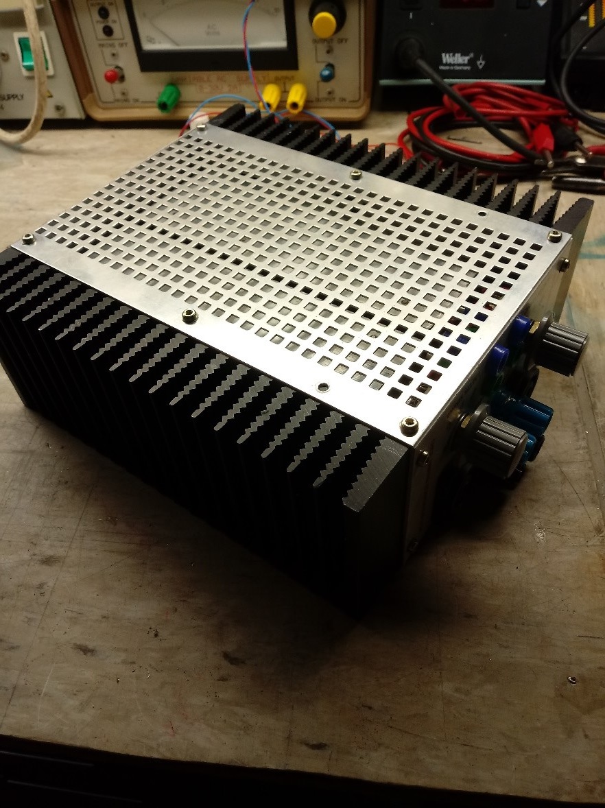
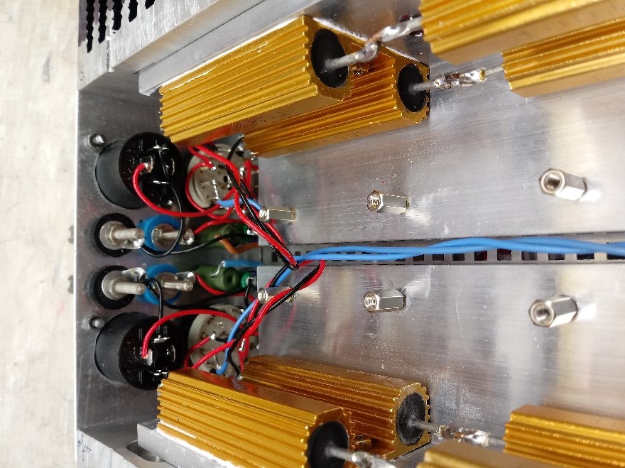
Construction consists of two identical heat sinks with the load resistors mounted to these. In my case I am using scrap heatsinks which had some surface defects; therefore, I mounted my resistors to aluminium angle (I did not have any flat bar at the time), then mounting this onto the heatsink. The angle was of a thickness suitable to transfer the heat from the resistors to the heat sink surface. Mounting of the resistors to the angle, and the angle to the heatsink required the use of a heat sink compound, I had a supply of Dow Corning paste so used that.
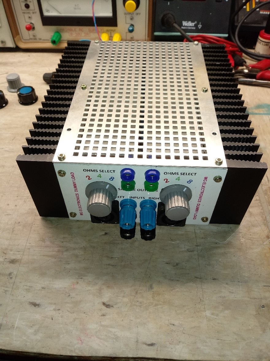
The Two heatsinks were secured into a box like construction using flat aluminium sheet to create the top, bottom, front and rear as individual parts. The heatsink was drilled and tapped to allow these to be attached. The front panel was punched to accept the hardware. You may choose a layout to suit your components and requirements, my inputs are speakon connectors with binding posts wired in parallel. The sample outputs chosen were 4mm test sockets and the selector switches are double pole 3-way rotary. If you intend using higher wattage, then switches capable of the high currents must be chosen. |
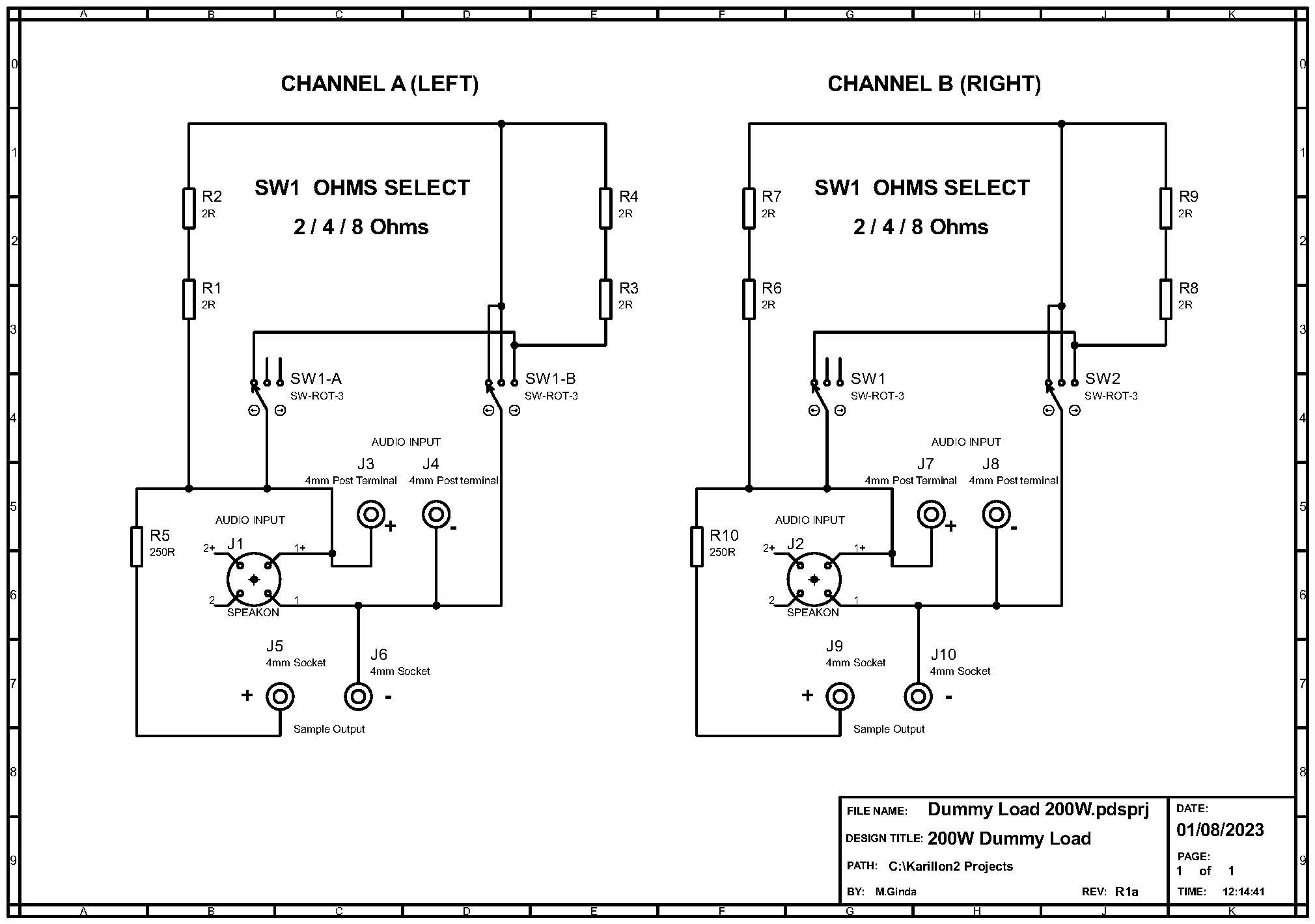
Schematic Diagram |
 |
| |
| Finished project. |
| |
 |
|
 |
|
You can download the full article as a pdf file by right clicking or selecting HERE and choose the save or view/open option.
Article and design Copyright © M.Ginda 2023
A note about copyright......I have tried to find publishers or anyone i can get, but some of this content is very old now. If you see your work here and it's an issue, contact me. I will either change, acknowledge or remove it.
(site policy here)
Copyright © M.Ginda 2023