Projector Rotator Speed Control
This page gives details for motor speed control of effects rotators, both standard AC sunchronous motor control, and a replacement dc motor with control circuitry to operate from either AC or DC input.
This first part of the project details the speed control circuitry used to vary the rotaional speed of a DC motor driving a gearbox of the same ovoid shape and outline as the original AC Synchronous motors fitted to most 6" effect wheel motor plates as used on Opti / Pluto / meteor product. The electronics use mostly surface mount components to reduce the overal pcb size making a fitting onto a modified motor plate simpler. |
|||||
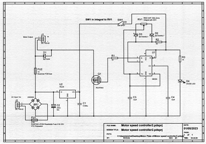
Here is the Schematic for the motor control. input requirements are:- DC 11v to 16v max AC 10v to 14v max These asume a dc motor with 12v dc requirement is attached to the gearbox. If a lower votage motor is used, a low drop type voltage regulated of suitable voltage can be inserted between the bridge and fuse FU2. FU1 provides protection should the bridge or main circuit fail and FU2 is solely for the dc motor, and its value can be chosen dependant on motor current. The prototype was constructed on a double side pcb 2.5 x 1.5cm in size. You may choose through hole components to construct this circuit on veroboard or similar prototype pcb material. |
 |
||||
Description: The input eother AC or DC is applied to the bridge rectifier BR1, the output of which is then a DC voltage smoothed by capacitor C2. This DC is fed to the motor positive via fuse FU2. Q1 connects the the motor negative to the negative voltage rail and recieves pulses via R1 to turn it on and off with varying pulse width derived from the oscilator circuit built around U1, a simple 555 timer IC. The timer ic circuit is powered seperately from a 5v regulated supply provided by U2 voltage regulator who has its supply fed from the bridge output. Capacitor C1 ensures the supply is smoothed and the timer is switched on or off via SW1 (this can be omited if not required), R3 and D4 indicate 'power on'. RV1 controls the pulse width therefore the motor speed, the main timing of the circuit is by C3.
|
|||||
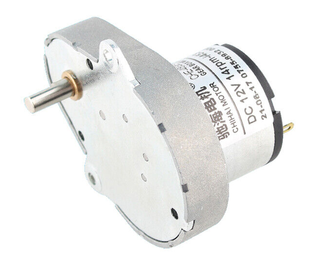
Shown here is the motor type similar that used. This a DC motor with gearbox reduction giving a final rotation speed of 14rpm. This allows the control to reduce speed down to 1/2 or 1rpm approximate. Choose a motor with gearbox having an output spindle of 4mm diameter. Other final speeds are ok but would suggest no faster than 20rpm as this compromises the lowest speed possible, a lower speed output (say 8 or 10rpm) will give better low speed settings if this is your aim.. There are many suppliers for this type of motor at very reasonable cost. |
..... |
||||
| Mount this motor to your motor plate and fix the control circuit to a bracket or house in a small plastic enclosure fixed to the plate. | |||||
 |
|||||
Part 2. Controlling the speed of the standard AC Synchronous motors as fitted to opti etc motor plate. |
|||||
Shown here is a typical motor used on Opti and similar effect motor plates. These are typically 12v AC synchronous motors with a gearbox giving a range of output speeds, such as 1/2rpm standard 6" wheel and 5rpm standard cassette. The motors are usually rated at 4watt approximately. |
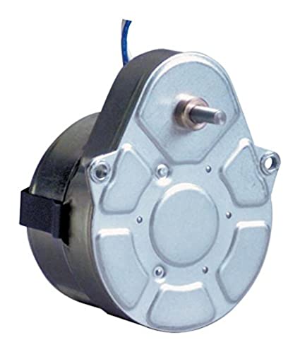 Crouzet synchronous motor, 4mm shaft. Crouzet synchronous motor, 4mm shaft. |
||||
Control of the synchronous motor is not as simple as the dc circuit above. Synchronous motors are speed governed by the ac frequency applied to the motor. To change the speed you must change the frequency of the ac feed. This is achieved by firstly converting the AC feed to a smoothed DC that is used to power both a coil driver circuit and a variable frequency oscilator. |
|||||
Copyright © M.Ginda 2023